Standards and scope
Standards and application range
Standards sets, voltage levels, bus schemes and plant types of SubstationLayout. A project takes one standards set.
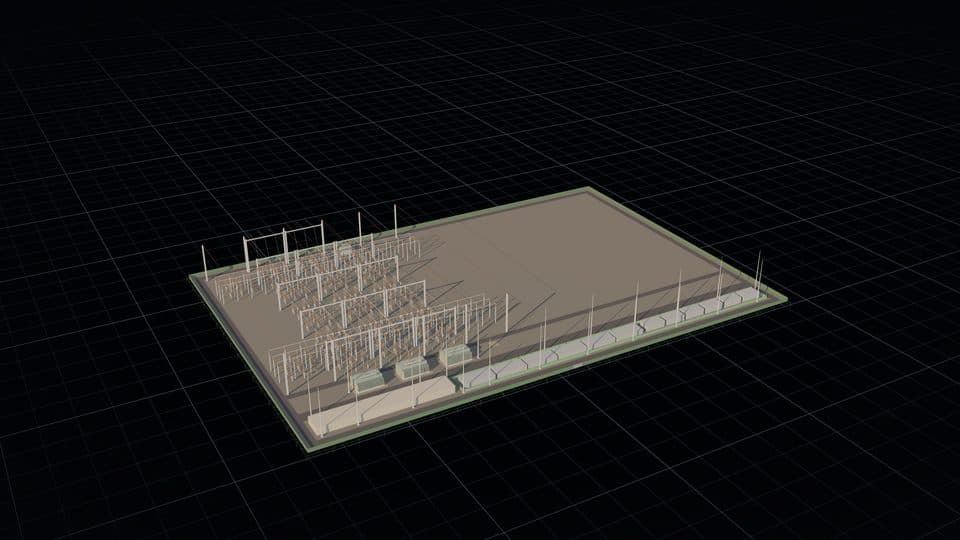
Application range
Substation types and arrangements per standards set
IEC, CEA and CBIP
- Pooling substations for wind, solar, hybrid, thermal and other plants
- HV: 33 kV, 66 kV, 132 kV, 220 kV and 400 kV, and 765 kV for switching. MV: 11 kV and 33 kV
- Switching (HV/HV) substations from 132/33 kV to 765/400 kV, with auto-transformers at 220 kV and 400 kV and banks of single-phase units at 765 kV
- Generator bays with generator transformers, station transformers and an 11 kV station board for synchronous plants
- Double main bus, one-and-a-half breaker, single sectionalised bus and single bus schemes
- Air-insulated (AIS) or gas-insulated (GIS) switchgear per HV yard, GIS in an indoor hall with SF6/air bushings
- MV indoor switchgear or outdoor AIS
- Line bays, transformer bays, bus coupler, bus reactor, switchable line reactors at 765 kV and future bays
- Static var generators and harmonic filters on the MV bus
- Soil resistivity from Wenner measurements
- 50 Hz or 60 Hz. A1 sheets, metric units
ANSI, IEEE and NESC
- Pooling substations for wind, solar, hybrid and other inverter-based plants
- HV: 69 kV, 115 kV, 138 kV, 161 kV, 230 kV and 345 kV. Collector bus: 34.5 kV
- Switching (HV/HV) substations: 345/230 kV, 345/138 kV, 345/115 kV, 230/138 kV, 230/115 kV, 230/69 kV, 161/69 kV, 138/69 kV and 115/69 kV
- Autotransformers at 230 kV and 345 kV with a 13.8 kV tertiary
- Ring bus with 3 or 4 circuit positions, one-and-a-half breaker, double main bus, single sectionalised bus and single bus schemes
- AIS or GIS switchgear per HV yard. Ring bus on AIS
- 34.5 kV indoor switchgear or outdoor AIS
- Line bays, transformer bays, bus coupler, bus reactor and future bays
- STATCOM on the 34.5 kV bus, sized at 0.95 power factor at rated output (FERC Order No. 827), a value for the reactive power study
- IEEE 693 qualification level as an input, printed on the yard notes and the BOM
- Soil resistivity from Wenner measurements
- 60 Hz. ANSI D sheets, feet and inches, AWG and kcmil
Voltage levels
Voltage levels and ratings per standards set
Rated values at the level. The bus scheme is the default on a new project, and you select another on the HV switchyard page. Plant capacity and transformer sizes are the design's values, not a standard's.
ANSI, IEEE and NESC
| Nominal HV | Rated maximum | BIL | Design fault level | Default bus scheme | Plant capacity | Transformer sizes |
|---|---|---|---|---|---|---|
| 69 kV | 72.5 kV | 350 kV | 31.5 kA | Ring bus | 20–60 MW | 20–50 MVA |
| 115 kV | 123 kV | 550 kV | 40 kA | Ring bus | 50–150 MW | 40–100 MVA |
| 138 kV | 145 kV | 650 kV | 40 kA | Ring bus | 50–200 MW | 40–120 MVA |
| 161 kV | 170 kV | 750 kV | 40 kA | Ring bus | 80–250 MW | 60–150 MVA |
| 230 kV | 245 kV | 900 kV | 50 kA | One-and-a-half breaker | 150–290 MW | 100–168 MVA |
| 345 kV | 362 kV | 1300 kV | 50 kA | One-and-a-half breaker | 300–1000 MW | 315 MVA, split LV |
Rated maximum voltage, BIL and fault levels per IEEE C37.04-2018 Tables 6, 12 and 16.
IEC, CEA and CBIP
| Nominal HV | Rated maximum (Um) | BIL | Design fault level | Default bus scheme | Plant capacity | Transformer sizes |
|---|---|---|---|---|---|---|
| 33 kV | 36 kV | 170 kV | 25 kA | Single sectionalised bus | 5–25 MW | 5–20 MVA |
| 66 kV | 72.5 kV | 325 kV | 31.5 kA | Single sectionalised bus | 20–50 MW | 20–50 MVA |
| 132 kV | 145 kV | 650 kV | 40 kA | Double main bus | 50–150 MW | 31.5–100 MVA |
| 220 kV | 245 kV | 1050 kV | 50 kA | Double main bus | 150–300 MW | 100–250 MVA |
| 400 kV | 420 kV | 1425 kV | 63 kA | One-and-a-half breaker | 500–1000 MW | 160–315 MVA, split LV |
| 765 kV | 800 kV | 2100 kV | 50 kA | One-and-a-half breaker | Switching | 1500 MVA |
Standards
Standards and editions applied
A year names the edition the design applies, which may precede the current edition. An entry with no year names the standard without an edition. Transformer sizes, yard geometry and several size lists are the design's values. The compliance checklist states the criterion, the design value and a status per item, and you answer the manual items.
ANSI, IEEE and NESC
| Standard | Applied to |
|---|---|
| IEEE C37.010-2016 | Short-circuit duty, E/X method |
| IEEE C37.04-2018 | Rated maximum voltage, BIL and breaker ratings |
| IEEE C37.13-2015 | Low-voltage power circuit breaker frames |
| IEEE 80-2013 | Grounding method |
| IEEE 998-2012 | Rolling sphere, HV yard |
| IEC 62305-3 | LPL I sphere, building and MV areas |
| IEEE 485-2020 | Battery sizing |
| IEEE 946-2020 | Charger sizing |
| NESC, ANSI C2-2007 | Rules 110A and 124A: fence and live parts |
| RUS Bulletin 1724E-300 | Clearances and phase spacing (Tables 4-7 and 4-8), from ANSI C37.32-1996 and NEMA SG-6-1995 |
| IEEE C37.2-1996 | Device numbers, as RUS Bulletin 1724E-300 Appendix F reprints them |
| IEEE C57.13-1993 | Instrument transformers, as RUS Bulletin 1724E-300 §5.10 reprints it |
| IEEE C57.12.10-1988 | Transformer impedance at 69 kV to 161 kV, as RUS Bulletin 1724E-300 Table 5-11 reprints it |
| FERC Order No. 827 | Reactive power at 0.95 power factor |
IEC, CEA and CBIP
| Standard | Applied to |
|---|---|
| IEC 60909-0:2016 | Short-circuit currents |
| IEEE 80-2013 | Earthing method |
| IEEE 998-2012 | Rolling sphere, HV yard |
| IEC 62305-3 | LPL I sphere, building and MV areas |
| IEEE 485-2020 | Battery sizing |
| IEEE 946-2020 | Charger sizing |
| IEC 60947-2 | ACB and MCCB ratings |
| ISO 8528-5 | DG set motor-start dip, class G3 |
| IEC 61869 | Instrument transformers |
| IEC 62271-203:2022 | GIS checklist items |
| IEC 60071-1:2019 | GIS checklist items |
| IEC 81346 | Designations on the SLD |
| IEC 60617 | Symbols on the SLD |
| CEA, CBIP | Clearances and checklist items |