Earthing and grounding design per IEEE 80-2013
Earth-mat and ground grid design for AIS and GIS substations in uniform soil: tolerable voltages, conductor size, grid resistance, mesh and step voltages. The documents are a layout, typical details and a report.
Calculations and documents
The grid is checked against the tolerable touch and step voltages of IEEE 80-2013. The results go to the layout, the report and the bill of materials.
- Surface derating factor per IEEE 80 §7.4 Eq. 27
- Tolerable touch and step voltages per IEEE 80 §8.3: Eq. 29 and 32 (50 kg) or Eq. 30 and 33 (70 kg)
- Conductor size per IEEE 80 §11.3.1 Eq. 37
- Decrement factor and grid current per IEEE 80 §15.10 Eq. 79 and §15.1 Eq. 63–64
- Grid resistance per IEEE 80 §14.2 Eq. 52
- Ground potential rise per IEEE 80 §16
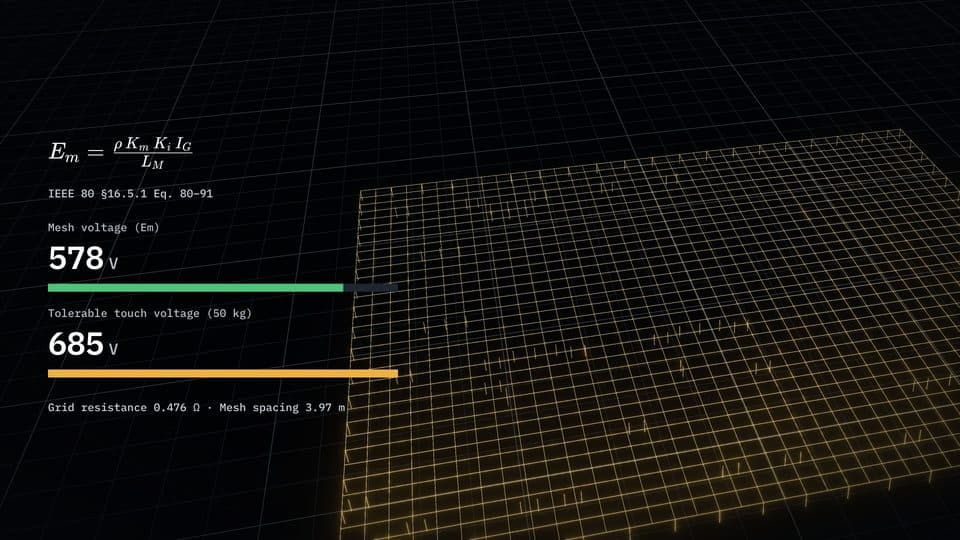
- Mesh voltage per IEEE 80 §16.5.1 Eq. 80–91, and step voltage per §16.5.2 Eq. 92–94
- Mesh spacing selected by the design
- Electrodes at the perimeter, surge arresters, instrument transformers, neutral points, lightning masts and shield-wire towers
- Soil resistivity entered or from Wenner measurements, with a season factor
- Surface layer resistivity and thickness
- Fault current and durations, current split factor and X/R
- Burial depth, ambient temperature and electrode size
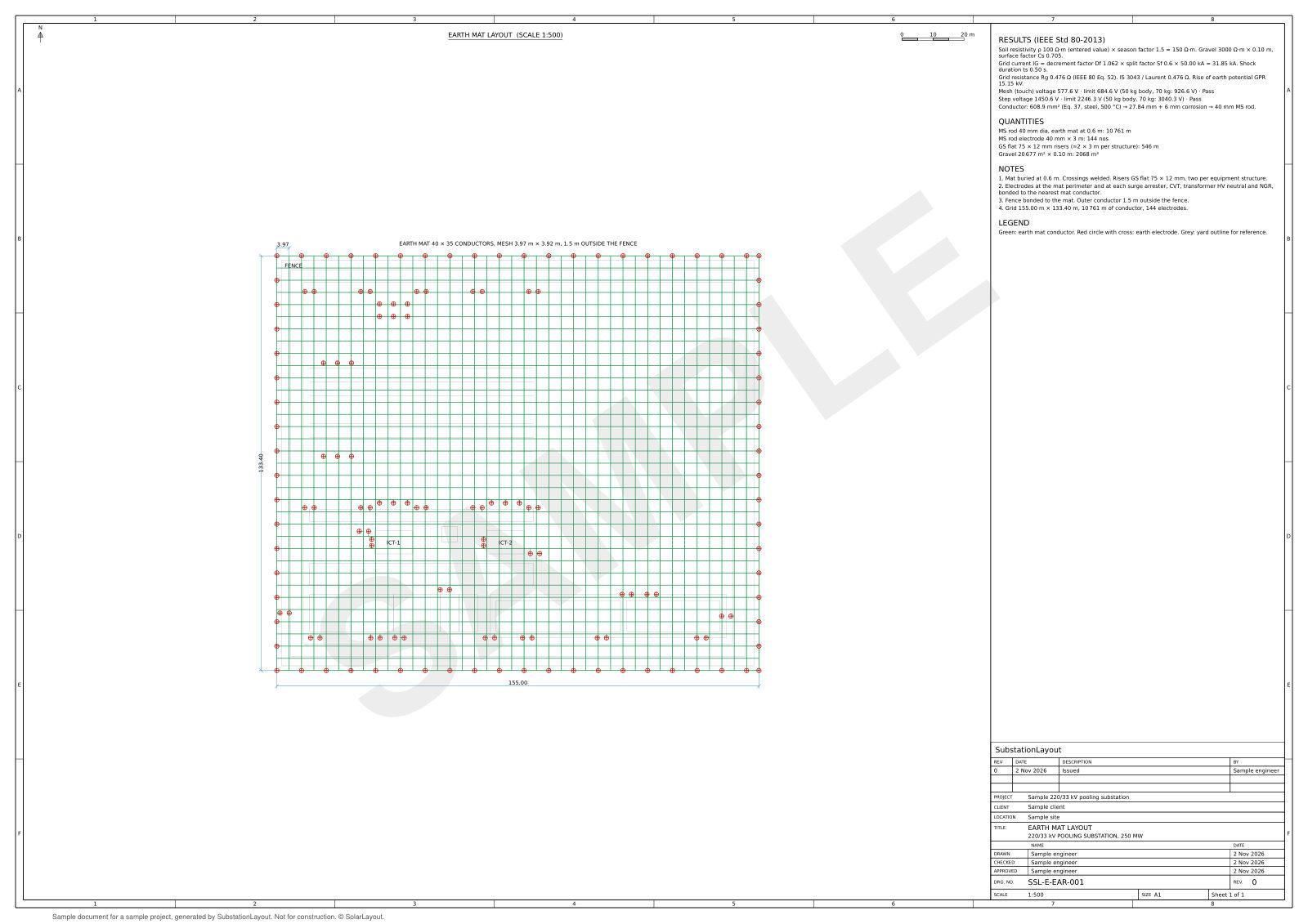
- Layout in DXF and PDF
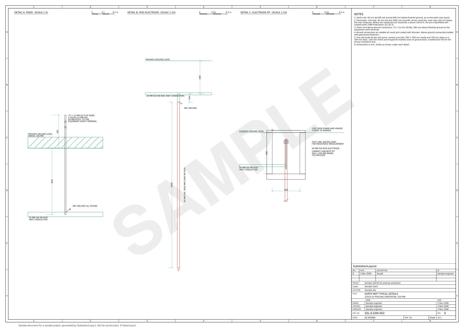
- Typical details in DXF and PDF
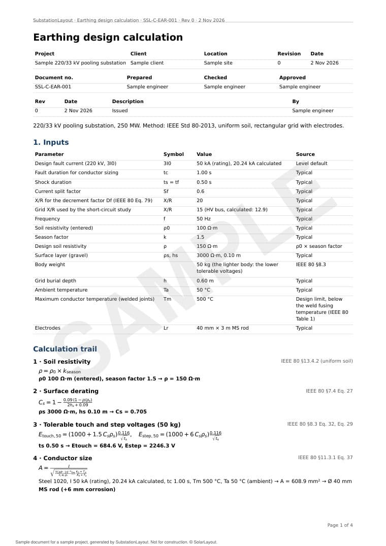
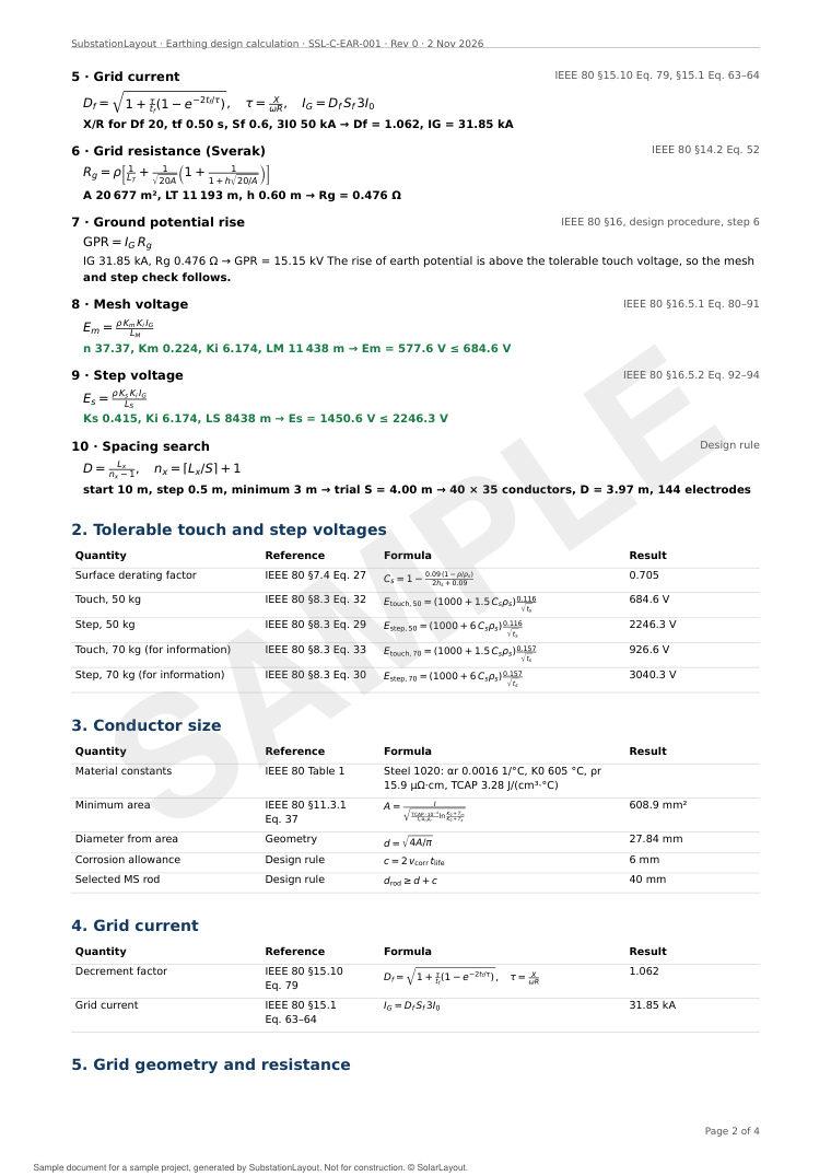
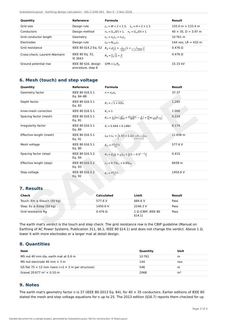
- Calculation report in PDF: inputs, calculation trail, results and quantities
- Quantities in the bill of materials
Materials and criteria per standards set
The IEEE 80-2013 method applies on both sets. The materials, sizes, body weight and words follow the standards set of the project.
| Item | IEC, CEA and CBIP | ANSI, IEEE and NESC |
|---|---|---|
| Words on the documents | Earthing, earth mat | Grounding, ground grid |
| Verdict | 50 kg body, 70 kg for information | 70 kg body, 50 kg for information |
| Conductor | Mild steel rod, with a corrosion allowance | Annealed soft-drawn copper, 4/0 AWG to 1000 kcmil |
| Electrodes | 40 mm × 3 m mild steel rods | 3/4 in × 10 ft copper-clad steel rods |
| Burial depth, new project | 0.6 m | 18 in |
| Connections and typical details | Welded joints, riser, rod electrode and electrode pit | Exothermic connections, riser, rod electrode and test well |
| Sheets | A1, metric | ANSI D, feet and inches, from 1″ = 20′ |
Results, 220/33 kV pooling substation
The mesh and step voltages are below their tolerable limits for a 50 kg body. Sample design per IEC, CEA and CBIP.
- Design soil resistivity (ρ)
- 150 Ω·m
- Grid size
- 155.0 m × 133.4 m
- Conductors
- 40 × 35, mesh spacing 3.97 m
- Electrodes
- 144, 40 mm × 3 m
- Grid current (IG)
- 31.85 kA
- Grid resistance (Rg)
- 0.476 Ω
- Ground potential rise (GPR)
- 15.15 kV
Equation, input values, result and clause per step
The calculation trail shows how the design reaches its results, in the order of the IEEE 80 design procedure.
- 1Soil resistivityIEEE 80 §13.4.2 (uniform soil)ρ0 100 Ω·m (entered), season factor 1.5ρ = 150 Ω·m
- 2Surface deratingIEEE 80 §7.4 Eq. 27ρs 3000 Ω·m, hs 0.10 mCs = 0.705
- 3Tolerable touch and step voltages (50 kg)IEEE 80 §8.3 Eq. 32, Eq. 29ts 0.50 sEtouch = 684.6 V, Estep = 2246.3 V
- 4Conductor sizeIEEE 80 §11.3.1 Eq. 37Steel 1020, I 50 kA (rating), 20.24 kA calculated, tc 1.00 s, Tm 500 °C, Ta 50 °C (ambient)A = 608.9 mm² → Ø 40 mm MS rod (+6 mm corrosion)
- 5Grid currentIEEE 80 §15.10 Eq. 79, §15.1 Eq. 63–64X/R for Df 20, tf 0.50 s, Sf 0.6, 3I0 50 kADf = 1.062, IG = 31.85 kA
- 6Grid resistance (Sverak)IEEE 80 §14.2 Eq. 52A 20 677 m², LT 11 193 m, h 0.60 mRg = 0.476 Ω
- 7Ground potential riseIEEE 80 §16, design procedure, step 6IG 31.85 kA, Rg 0.476 ΩGPR = 15.15 kV The rise of earth potential is above the tolerable touch voltage, so the mesh and step check follows.
- 8Mesh voltageIEEE 80 §16.5.1 Eq. 80–91n 37.37, Km 0.224, Ki 6.174, LM 11 438 mEm = 577.6 V ≤ 684.6 V
- 9Step voltageIEEE 80 §16.5.2 Eq. 92–94Ks 0.415, Ki 6.174, LS 8438 mEs = 1450.6 V ≤ 2246.3 V
- 10Spacing searchDesign rulestart 10 m, step 0.5 m, minimum 3 mtrial S = 4.00 m → 40 × 35 conductors, D = 3.97 m, 144 electrodes
Earthing calculation report
The report states the inputs and their sources, the calculation trail, the results against their limits and the quantities.