Single-line diagram
Single-line diagram
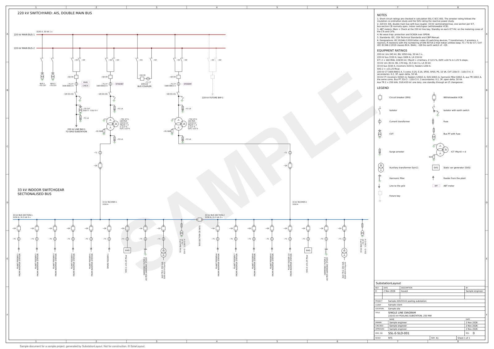
The single-line diagram is drawn from the design inputs: bus scheme, bays, transformers, instrument transformers and MV bus sections. The design sets their ratings.
Capabilities
Diagram content and output
The diagram sets the circuit arrangement that the yard layout, the 3D model and the bill of materials follow. Its objects are linked to those surfaces.
Circuits
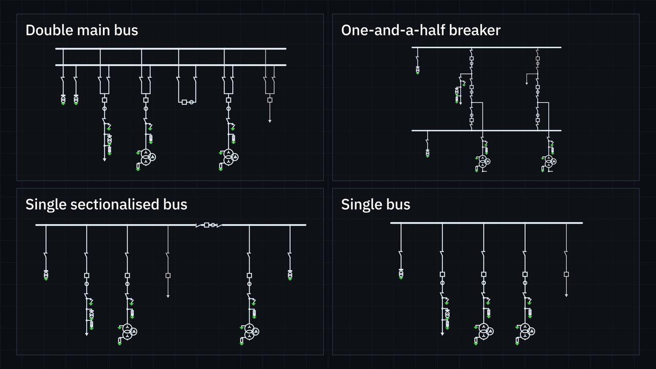
- Bus schemes per standards set, below
- Line bays, transformer bays, bus coupler, bus reactor and future bays
- MV indoor switchgear or outdoor AIS, with bus sections
- Reactive power device and harmonic filters on the MV bus
Drawing
- Designations per standards set, below
- Instrument transformer ratios
- Title block and revision table
- Output in DXF and PDF
- Selection linked to the yard layout, the 3D model and the BOM
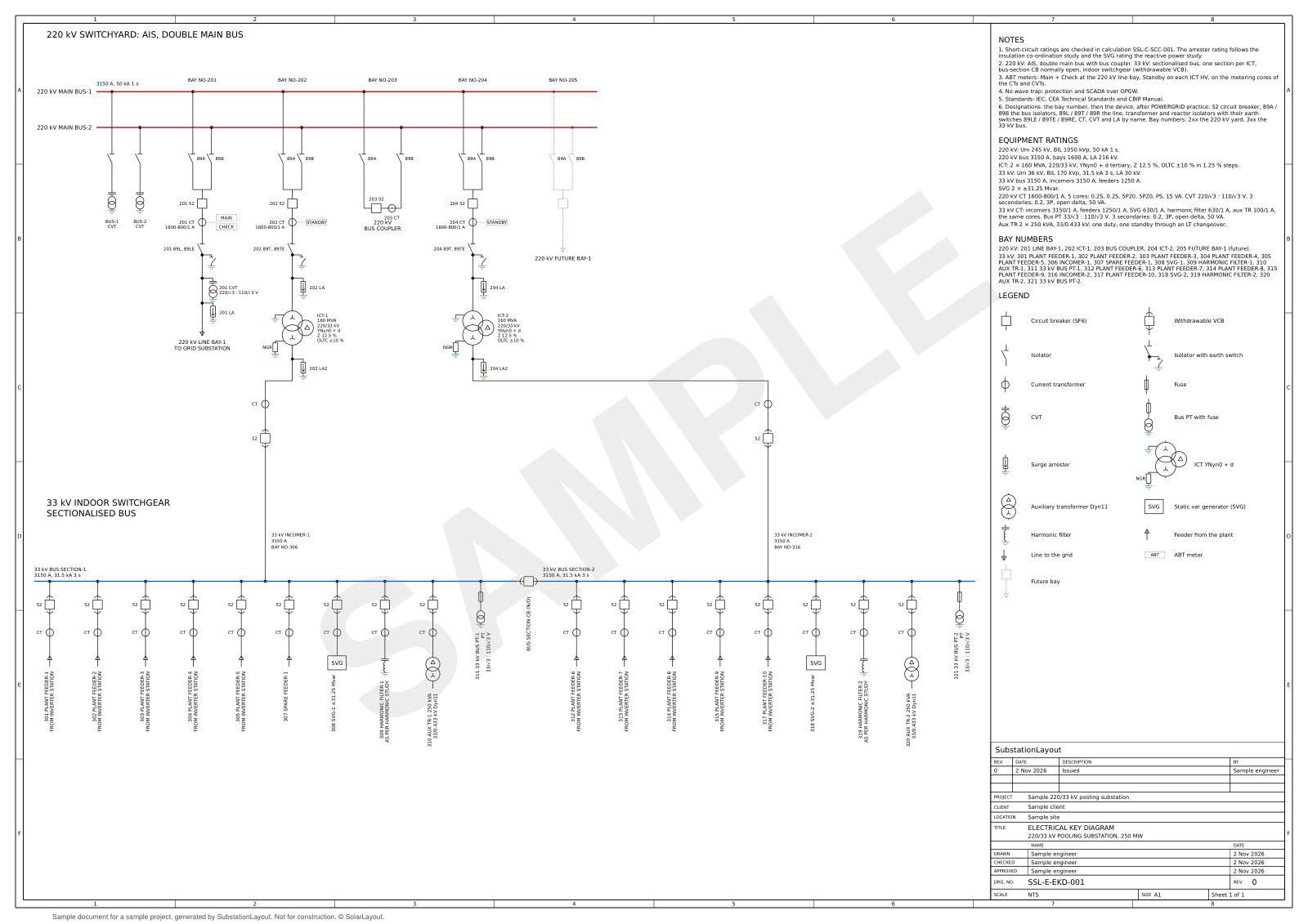
Electrical key diagram
- Bays numbered and devices tagged by bay
- Numbering per standards set, below
- Output in DXF and PDF
Standards sets
Designations and equipment per standards set
The diagram follows the standards set of the project: its designations, instrument transformers, bus schemes and equipment names.
| Item | IEC, CEA and CBIP | ANSI, IEEE and NESC |
|---|---|---|
| Designations | IEC 81346 designations, IEC 60617 symbols | IEEE C37.2-1996 device numbers: 52, 89 |
| Key diagram numbering | POWERGRID practice ("201 52", "BAY NO-201") or IEC 81346 ("=E01−Q0") | IEEE C37.2-1996 device numbers by bay ("52-101", "89L-101") |
| Instrument transformers | CT, CVT and PT ratios, IEC 61869 | IEEE C57.13-1993: multi-ratio CTs, 5 A, C800 relaying and 0.15 metering classes, CCVTs at 115/√3 V |
| Bus schemes | Double main bus, one-and-a-half breaker, single sectionalised bus, single bus | Ring bus, one-and-a-half breaker, double main bus, single sectionalised bus, single bus |
| Transformers | ICT with OLTC, YNyn0 + d | LTC, cooling stages ONAN/ONAF/ONAF. YNyn0 + d main transformers, YNa0d1 autotransformers, Dyn1 station service transformers |
| MV bus device | Static var generator and harmonic filters | STATCOM and harmonic filters |
Sample project
Single-line diagram, 220/33 kV pooling substation
Sample design per IEC, CEA and CBIP.
- HV bays
- 4 + 1 future
- MV outgoing feeders
- 19
- MV panels
- 23
Drawings
Single-line diagram and electrical key diagram
Documents of a sample project, generated by SubstationLayout and marked as samples. Not for construction.