Auxiliary supply and station service
Auxiliary supply and station service
The AC and DC auxiliary systems of the substation: load list, transformer, generator, battery, chargers and switchgear ratings. The schematic and the report are sample documents.
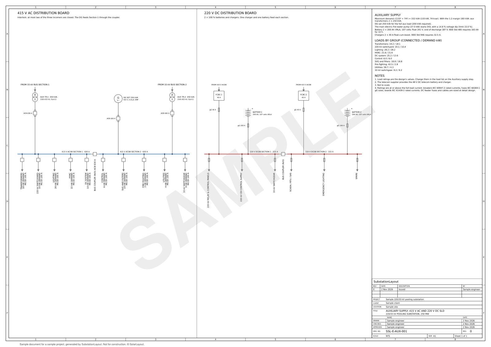
LT / DC auxiliary schematicSSL-E-AUX-001 · Rev 0 · 1 page · PDF · 38 KB
DownloadCapabilities
Auxiliary calculations and documents
The design builds the load list from the substation, and you can edit it. The sizes follow from the maximum demand and the DC duty cycle.
AC system
- Load list with duty factors and maximum demand
- Transformer sizing
- Generator sizing and motor-start dip
- Breaker ratings per standards set, below
DC system and documents
- DC duty cycle per IEEE 485 §5
- Battery sizing per IEEE 485 §6
- Charger sizing per IEEE 946
- LT / DC or station service schematic in DXF and PDF
- Calculation report in PDF
Standards sets
AC and DC systems per standards set
The voltages, the switchgear and the generator follow the standards set of the project.
| Item | IEC, CEA and CBIP | ANSI, IEEE and NESC |
|---|---|---|
| AC | 415 V, ACB and MCCB ratings per IEC 60947-2 | 480Y/277 V, breaker frames per IEEE C37.13-2015 §5.4 |
| Generator | DG set, motor-start dip per ISO 8528-5 (class G3) | Standby generator with an automatic transfer switch, motor-start dip |
| DC | 220 V DC, battery per IEEE 485-2020, chargers per IEEE 946-2020 | 125 V DC, vented lead-calcium, 8 h duty, battery per IEEE 485-2020, chargers per IEEE 946-2020 |
Sample project
Results, 220/33 kV pooling substation
The motor-start dip is within its limit. Sample design per IEC, CEA and CBIP.
- Connected load
- 248.4 kW
- Maximum demand
- 133.0 kW, 152.2 kVA
- Auxiliary transformers
- 2 × 250 kVA
- DG set
- 250 kVA
- Motor-start dip
- 14.8 %
- Battery sets
- 2
- Chargers
- 2
Calculation trail
Equation, input values, result and clause per step
The calculation trail shows how the design reaches its sizes, from the maximum demand to the switchgear ratings.
- 1Maximum demandDesign rule25 loads, connected 248.4 kWP = 133.0 kW, Q = 74.0 kvar, S = 152.2 kVA
- 2Auxiliary transformerDesign rulerequired 182.7 kVA2 × 250 kVA (one duty, one standby)
- 3DC duty cycleIEEE 485 §54 periods, 107 cells at 240.8 V floatcontinuous 10.5 A
- 4Cell sizing sectionsIEEE 485 §6.34 sectionslargest section 118.8 Ah
- 5Battery capacityIEEE 485 §6.4required 163.4 Ah2 × 200 Ah C10
- 6ChargersIEEE 946L 10.5 A, C 200 Ah2 × 40 A float-cum-boost, 11.6 kW each
- 7DG set and motor-start dipISO 8528-5 (class G3)required 199.5 kVA, largest motor Electric fire-water pump (main) 37 kW250 kVA, dip 14.8 %
- 8Switchgear ratingsIEC 60947-2, IEC 60269-1, IEC 61439-218 devices at 415 V and 220 V DCACDB 630 A, DCDB 315 A
Document
Auxiliary supply calculation report
The report states the load list, the transformer, the DG set, the battery, the chargers and the assumptions.
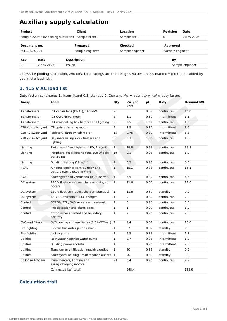
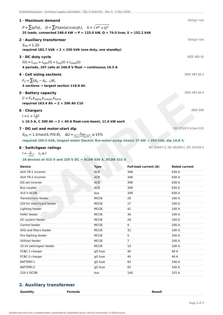
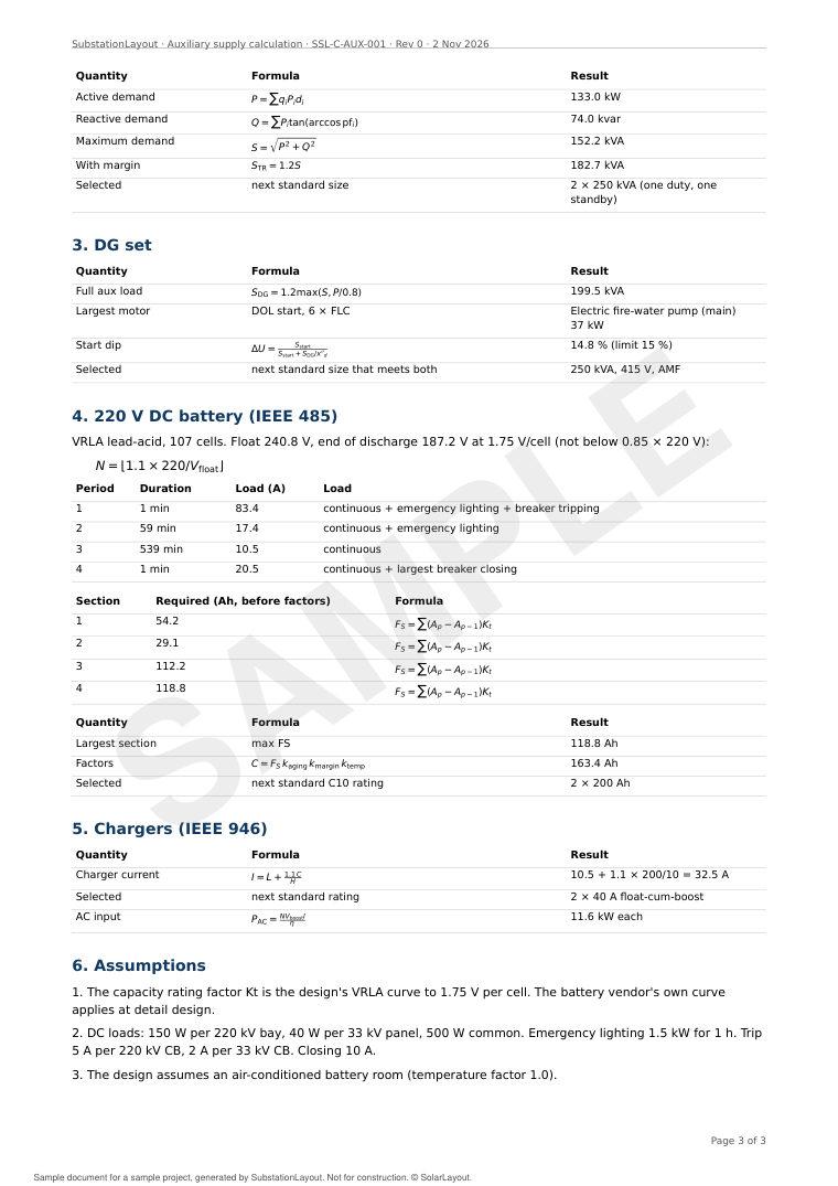
Auxiliary supply calculation reportSSL-C-AUX-001 · Rev 0 · 3 pages · PDF · 78 KB
Download