Direct stroke shielding by the rolling sphere
Direct stroke lightning protection (DSLP) shields the live parts of a switchyard against lightning strokes that would otherwise terminate on them. The Central Electricity Authority (CEA) Construction Regulations 2022 ask that the switchyard be shielded against direct lightning strokes by overhead shield wires, earth wires or masts (Reg. 44(2)(c)). The design checks the shielding by the rolling sphere method of IEEE Std 998-2012 (§6.6). This topic explains how the radius of the sphere is found for each protected level.
1The sphere and the protected level
A sphere is rolled over the ground, the shield wires and the masts. A point that the sphere cannot touch is protected (IEEE Std 998-2012 §6.6). The sphere's radius is the striking distance of the allowable stroke current , the smallest stroke current that can flash over the insulation of the protected level (§6.5). A stroke below that reaches the conductor does not flash over its insulation. Strokes with larger currents have larger striking distances, and the shield wires and masts intercept them. So the sphere depends on the protected level: its height, its conductor and its basic lightning impulse insulation level (BIL).
2The revised electrogeometric model
The design finds in four steps by the revised electrogeometric model of Mousa and Srivastava (IEEE Std 998-2012 §6.5). A conductor at height above the ground, of radius , carries the BIL of its level. Under the stroke's surge, corona forms around the conductor. The corona radius is the radius of that envelope at the BIL, with the corona inception gradient of 1500 kV/m for negative strokes.
Eq. (1) has no closed form. The design solves it for by bisection, between a small radius and , where the left side is largest. It takes no smaller than the conductor's radius .
The surge impedance of the conductor under corona takes the corona radius in one logarithm and the conductor's radius in the other.
| height of the protected conductor above the ground | m | |
| radius of the protected conductor | m | |
| basic lightning impulse insulation level of the protected level | kV | |
| corona inception gradient | kV/m | |
| corona radius | m | |
| the base of the natural logarithm | ||
| surge impedance of the conductor under corona | Ω | |
| allowable stroke current | kA | |
| striking distance factor | ||
| striking distance, the radius of the rolling sphere | m |
The factor is 1 for a shield wire. IEEE 998 allows 1.2 for a mast, which would protect a larger area. The design takes = 1 for the masts as well, so the mast coverage it shows is the smaller one.
Figure 1 shows the striking distance rising with the BIL. At the lowest BILs the sphere is smaller than the sphere of 20 m of IEC 62305-3 protection level I.
3Spheres of the protected levels
The design calculates a sphere for each protected level of the high-voltage (HV) yard from its own height, conductor radius and BIL. the table lists the levels of the default 220 kV project. The heights and the conductor radii are the design's values. The main bus is an aluminium tube of radius 57.15 mm. The equipment interconnection is aluminium conductor steel-reinforced (ACSR) Moose of radius 15.9 mm, as is the conductor at the bushing tops of the interconnecting transformers (ICT).
| Level | Method | Protected height | Sphere radius |
|---|---|---|---|
| HV tubular bus | IEEE 998 (Mousa) | 9.0 m | 29.15 m |
| HV equipment | IEEE 998 (Mousa) | 5.9 m | 28.97 m |
| ICT bushing tops | IEEE 998 (Mousa) | 7.5 m | 27.99 m |
| 33 kV outdoor areas | IEC 62305 LPL I | 5.5 m | 20.0 m |
| Control building roof | IEC 62305 LPL I | 6.0 m | 20.0 m |
The transformer bushing tops take a smaller sphere than the bus, at the same BIL. Their conductor is thinner than the bus's tube, which raises the surge impedance and lowers the allowable stroke current. A switching substation's lower yard takes its spheres from its own BIL in the same way.
4The sphere of IEC 62305-3
IEC 62305-3 Table 2 gives the rolling sphere's radius per lightning protection level (LPL), as the table lists. The design takes the sphere of LPL I, the smallest and so the most protective, for the MV outdoor areas, the control building's roof and the roof of a gas-insulated switchgear (GIS) hall.
| Lightning protection level | Sphere radius |
|---|---|
| I | 20 m |
| II | 30 m |
| III | 45 m |
| IV | 60 m |
The MV areas carry a BIL of 170 kVp. There the Mousa sphere is 7.8 m (IEEE Std 998-2012 §6.5). Masts at least that tall would stand no more than 11.0 m apart on a square grid to protect the ground (a protected height of 0 m), against 28.3 m for the sphere of 20 m. Both spacings are the sphere's radius times , derived from the geometry. When the HV level's own BIL is 170 kVp or less, the whole yard takes the LPL I sphere.
The IEC + CEA / CBIP set and the ANSI / IEEE set take the same spheres: the Mousa sphere for the HV yard and the LPL I sphere for the building and the MV areas.
5The rolling sphere over the yard
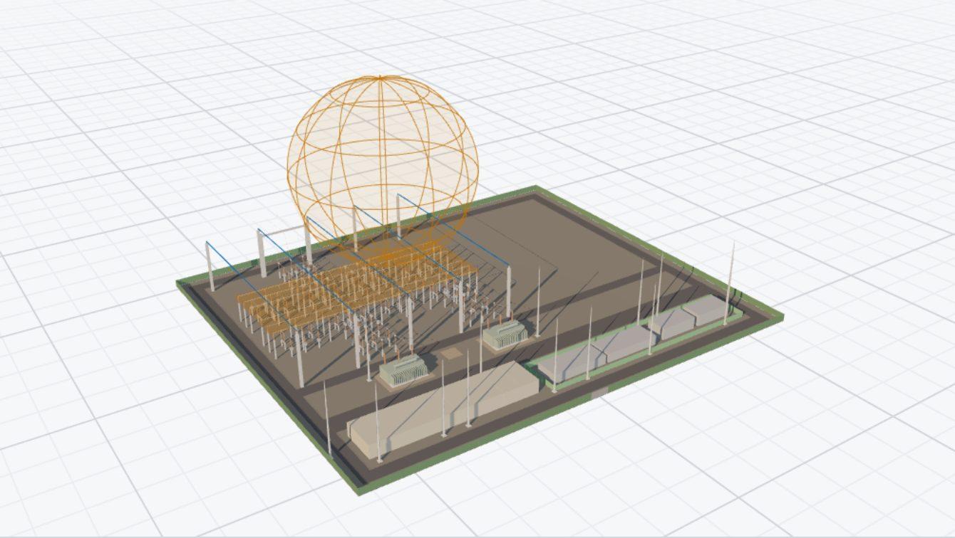
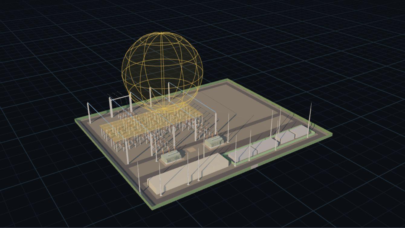
The design service builds the yard in three dimensions, with its lightning masts and shield wires. Figure 2 rolls the sphere of each protected level over that model and draws the level as a plane. A point that the sphere cannot touch without first touching a mast, a wire or the ground is protected (IEEE Std 998-2012 §6.6). For the default yard the sphere stays above each level at its protected points. The least margin is the smallest height between a level and the lowest point the sphere reaches over it.
Given the HV tubular bus of a new 220 kV project with the default inputs, as the design service calculates it.
| Quantity | Value |
|---|---|
| BIL | 1050 kVp |
| Bus height | 9.0 m |
| Tube radius | 57.15 mm |
| Corona inception gradient | 1500 kV/m |
| Striking distance factor | 1 |
Corona radius by Eq. (1), solved by bisection:
Surge impedance by Eq. (2):
Allowable stroke current by Eq. (3):
Striking distance by Eq. (4):
Result The rolling sphere of the HV tubular bus has a radius of 29.15 m. The HV equipment takes 28.97 m and the ICT bushing tops 27.99 m, from the same steps.
[1]IEEE Std 998-2012, IEEE Guide for Direct Lightning Stroke Shielding of Substations. §6.5.
[2]IEC 62305-3, Protection against lightning.
[3]CEA Construction Regulations 2022, Central Electricity Authority (Technical Standards for Construction of Electrical Plants and Electric Lines) Regulations, 2022.